Recent Posts
Categories
Tons of Parts!!
Posted on August 15th, 2006 by James.
Categories: Pinball.
The part delivery fairy has finally arrived!! WOOOOO!!!! 🙂 🙂 🙂
Check it out! I got tons of stuff in little tiny bags! I love little tiny bags full of stuff!
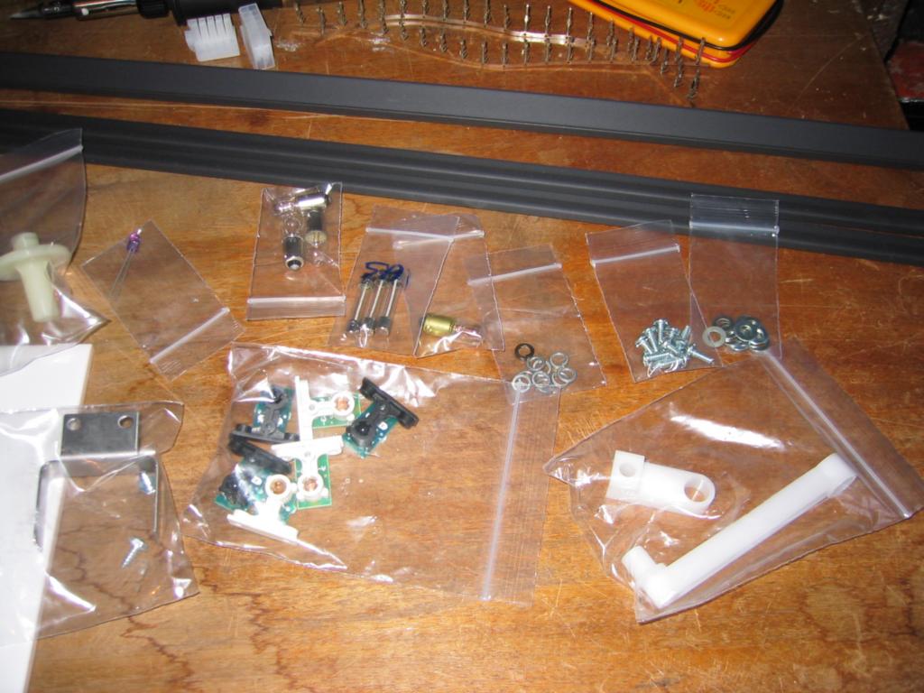
Fun stuff to playwith includes: Random washers and screws for screwing stuff (tee hee). The white arms for my cannon .. but not the triangle bit.. that’s coming from somewhere else. Light bulbs for my klingon battle-thing-a-mer-ship (what are they called?!) A shiny new fuse to make all my lights turn on! A metal U for screwing under the playfield to stop the ball totally smashing up the drop hole round the neutral zone (this is a really common place to have lots of wear apparently). A new Infra-Red LED, for the ball trough, because at the moment one of them is bust, so the machine thinks there is a ball missing! The white tube thing is the flipper bushing for the top flipper, or for non-pinball techs, it’s the bit the flipper sticks through as a bearing, because the old one snapped right in the middle! Not shown very well in this pic are the strips to hold my translite in… and finally, the most important bits.. my new optos!! The white T shapes are IR-LED emitters and the black ones are the detectors. The work in pairs and they detect the ball when it’s under the playfield.
So first I decided to do the simplist thing first to make everything look tons better, fitting the translite. The translite is the semi transparent picture that goes on the back box and at the moment the clips that hold it to it’s bit of glass are missing and/or snapped.
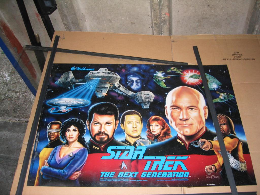 Here it is before I cut the side clips to size.
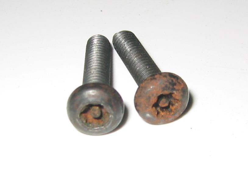
Fitting it requires unlocking the top lock on the back box and I noticed that the screws on the lock were looking really rusty, so I wipped out the auto-sol and gave them a quick polish. That stuff is amazing! Check out the pic. The screw on the left has just had a quick polish, the one on the right is still horribly rusty.
Now that the lock is fixed, we can do this! 🙂
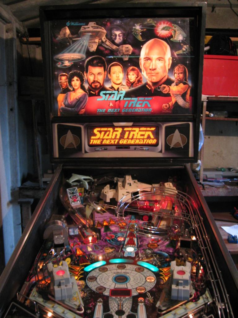
This is after I put in the fuse for the lighting too obviously 🙂 Doens’t it look awesome!
Next I fitted the Neutral zone protector, which you can’t really see very well so I didn’t bother with a pic.. and then my new trough LED
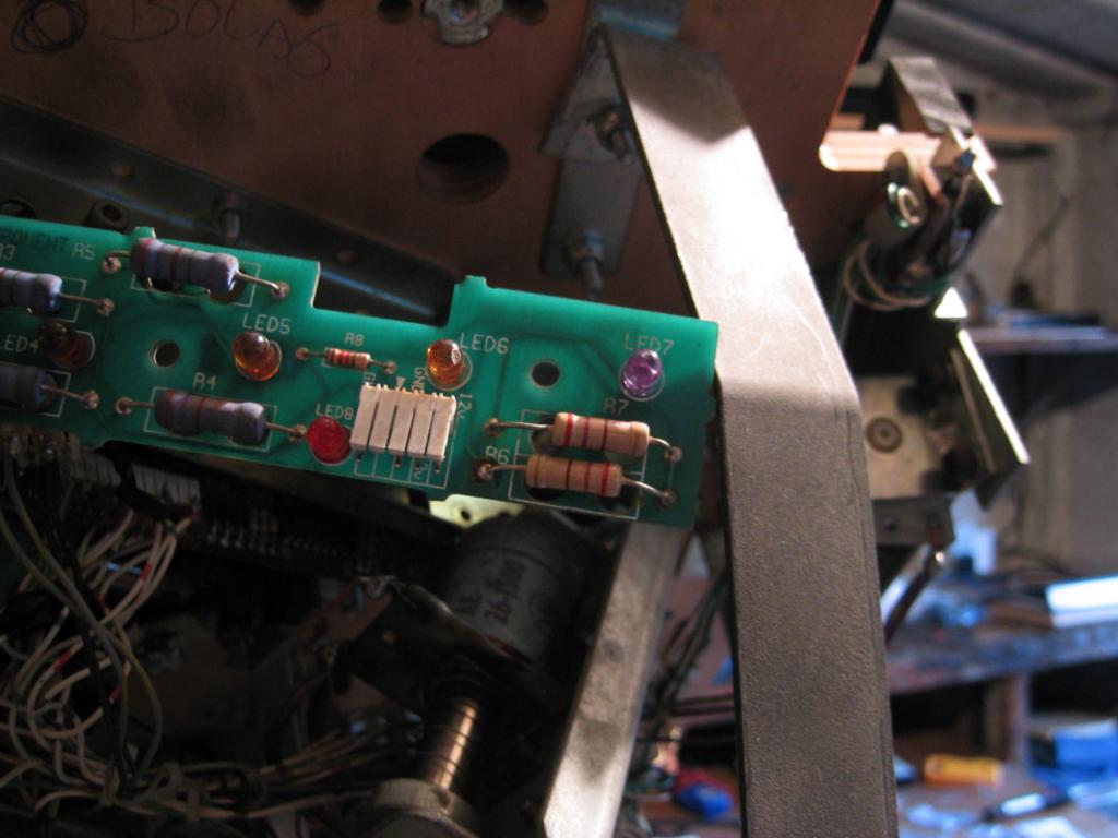
It’s the purple one on the right. Fitting it was a right pain in the arse, not because it was difficult to solder on, but it took ages to realise that I needed to put it on backwards! On the PCB there is a little marking that says which way to mount the LED, using the standard electrical LED picture of a circle with a flat edge. The LED itself is circular with a flat edge.. logically you’d match them up, right?! After all the old LEDs are matched up with their pictures.. but NO! You have to mount it the other way round!?!!! When I looked inside the glass of the new LED, I could see that the little metal bits inside it are the opposite way round to the old ones! If anyone knows why this has happened, since my machine was built in 1993, then please let me know!! I would have thought that changing the way electrical marking work would in general be a bad idea for everyone! I mean can you imagine the day that they did it.. Bob the electronic engineer goes to work one day and he’s just drawn up some huge diagram on a piece of paper the size of his entire desk, then his boss tells him the news from the meeting. “Hi Bob… I’m fine thanks. So that diagram, we’re going to have to make a teeny change.. .. uh huh.. yes, by ‘we’ I do mean you… yeah, so, we’d like you to draw all the LEDs facing the other way round…. no, seriously…. no, the test was negative.. yup.. other diagrams? Well yeah, I guess you will have to update all of them. .. uh huh, yep, before Friday.. yep, I know it’s Thursday afternoon… no, my parents are married. Thanks Bob”
Now to my optos. A tale of woe! I blew them up! :-(! After all that helpful info from AlexP, I ended up writing down the info wrong when I copied it from my email onto a piece of paper to take into the garage. I wired up one of the emitters to a grey-yellow cable instead of a grey-blue cable and checked to see if it was lit using my camera (as the LED is InfraRed).. but I couldn’t see anything. After a while I decided it was a duff LED, so I tried another one, which of course blew that one up too! Then I got out my multi meter and tested the power incase it wasn’t working.. but it was working fine, far too fine!! I’d fed the LED twice the voltage it was supposed to get and blown it up! 🙁 .. I went back to the computer and checked my notes again and found the right cables. I wired the the third LED correcly 🙂 Then I wired in all the rest of the optos, so now I just need to order two replacement IR-LEDs and all the cabling is ready
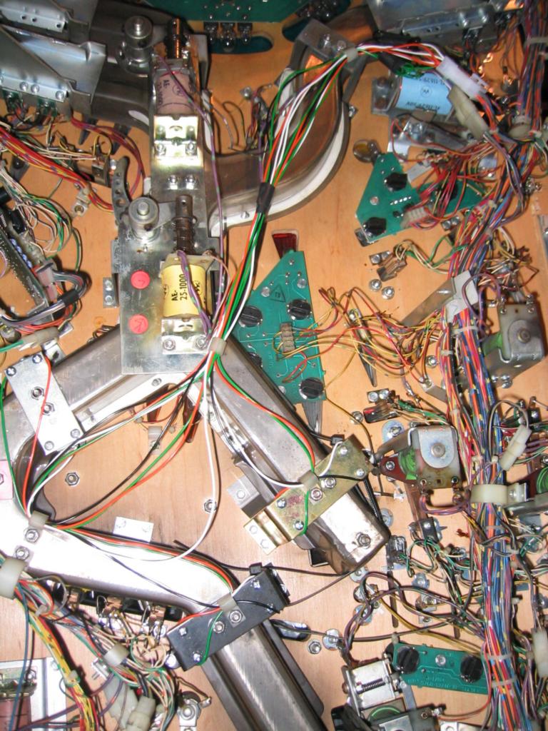
The new optos are the on either side of the rails with the Orange/Green/Black/White cables.
I’m really miffed about blowing them up! These and the cannon triangle are the only things left to fix (I think!), so if I’d got the optos working I would actually be able to vey nearly play a normal game!
So remember kids, always check the voltage before you plug stuff in! Or else POP! No more shiny electronics!
2 comments.
Lo
Comment on August 16th, 2006.
Cool yese it s really look awesome I look forward to trying it : )
As I told rachel I am already in french very crap with mecanique so you won’t mind no idea what you said in the last big part!
But well I am glad for you and it was ncice to read this blog : )
Francis
Comment on August 16th, 2006.
Cool… have to fly back and have a go when its working.. 11387.16 miles give or take a couple… to play pinball! it has to be worth it! 🙂
Leave a comment
Comments can contain some xhtml. Names and emails are required (emails aren't displayed).